 Data Display Software "Graph"
 Data Display Software "Graph"
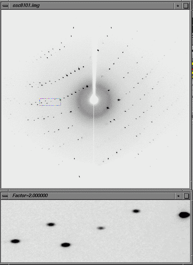
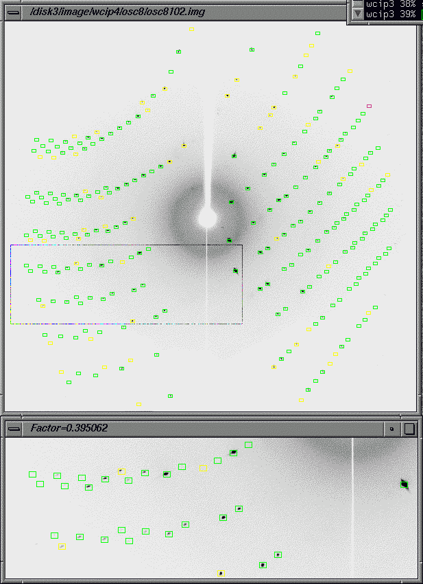
This software displays R-AXIS image data. When used in conjunction with various commands, this software can indicate diffracted X-ray locations, integrated intensity calculation range, and other information, thereby allowing the user to confirm the progress and status of data processing. Figure 1 shows the normal state. Figure 2 shows the state that prevails after "predic" execution. When "predic" is executed, the box for spot location indication is color-identified using the following three colors.

Figure 1 "graph" window

Figure 2 "graph" window (displayed after "Predic" execution)
The use and functions are explained below.
Functions

- Displays a diffraction image on a gray level or color level.
- Displays overload pixels (red).
- Resizes the main window (with the mouse).
- Displays an enlargement window (s key).
- Changes the enlargement window display location (by grabbing the main window with the mouse).
- Changes the enlargement window magnification (up/down arrow marking).
- Displays pixel intensities when an increased degree of magnification is used (when the -two option is specified).
- Inverts the image display level (r key).
- Changes the gray/color level (leftward/rightward arrow, 90(), , or b keys).
- Displays the pointer location (t key).
- Displays a 3D image (p key; when the -two option is specified).
- Displays simple usage instructions (? key).
- Displays pixel intensity in 2D (i key; when the -two option is specified).
- Displays peak search points (psearch program or xsend program).
- Displays calculated positions (predic, refosc, and integ programs or xsend program).
- Erases on-screen peak search points and calculated locations (o key).

Precautions

When operating the keyboard, be sure to check that the pointer is within a window.
No window supports the "close" and "exit" functions of Xwindow.
Therefore, if such a function is specified, the program is killed.

When calculated speck locations are displayed, the measurement box of the same size is displayed for all on-screen
specks.If variously sized boxes are used at the time of integrated reflection intensity calculations, their sizes
are not properly displayed.

Subcommands
-f f   Frame file name.  A frame file name is normally assigned using a template and frame serial number in
       "-t t -n n" form.  However, the use of a name portion only may also be permitted in some cases.  Within the
       program, management is exercised with a template and frame serial number.  The number portion of the name
       given here is interpreted as a serial number.  Therefore, when a frame template contains a number, the
       operation is not guaranteed.
-t t   Frame file template (e.g., test##.img).  This must be written using a full path or relative path.  By default,
       the template written in resource.dat is used.
-n n   Frame serial number.
-s s   Scanner type (RAXIS2, RAXIS4, BAS2000, RIGAKU, or RAXISS3).  The other names are regarded as the names of
       unknown scanners, which require the additional commands enumerated below.
-o o   Scan sequence code (+H+V, -H+V, +H-V, -H-V, +V+H, -V+H, +V-H, or -H-V).
-r r   Specifies the window rotation for image display (0, 90, or -90; 0 by default).
-p p   First bit-shift value (the default value varies with the scanner).
-swap  Implements byte swapping.
-two   Loads both of the two bytes of 2-byte pixel data.  If this option is not specified, only one byte is loaded for
       increased memory space savings.
-shared Reads the shared memory.
-spring8 Reads the shared memory for SPring8.
-no_frame Mode in which no frame data used.
-disable  Disables the drawing display function at startup.

Additional command for a special pixel size
-pixel_label label Character string that indicates a special pixel size (100x100, 200x200, 50x50, or 100x15).

Additional subcommands for unknown scanners
-length   length    Record length (in pixels).
-records  records   Number of records.
-header   header    Number of header bytes.
-bytes    bytes     Number of bytes per pixel.
-overload overload  Overload numerical value.
-pixelx   pixelx    Horizontal pixel size (in mm).
-pixely   pixely    Vertical pixel size (in mm).

Keyboard operations
Valid only when the pointer is placed within the associated window.

s               Toggles between subwindow display and erase.
c               Toggles between gray-scale display and color display.
o               Toggle switch used to temporarily hide on-screen spots.
b               Toggles between color bar (gray bar) display and erasure.  The color bar can be adjusted by dragging
                the displayed right or left line with the mouse.  It can also be repositioned by performing the
                following keying procedures ((, ), <, >, 9, 0, ",", or ".").
t               Toggles between pointer location window display and erasure.  The location is indicated in pixels with
                reference to the lower left-hand corner (origin) of the on-screen drawing.  Even if the drawing is
                rotated by the -r option, the lower left-hand corner serves as the origin.
r               Toggle switch for gray-scale inversion.
<-(left arrow)  Invokes a leftward 1-bit shift at the time of sampling (see note below).
->(right arrow) Invokes a rightward 1-bit shift at the time of sampling (see note below).
(               Shifts the left end of the color bar ten positions to the left.
)               Shifts the left end of the color bar ten positions to the right.
<               Shifts the right end of the color bar ten positions to the left.
>               Shifts the right end of the color bar ten positions to the right.
9               Shifts the left end of the color bar one position to the left.
0               Shifts the left end of the color bar one position to the right.
,               Shifts the right end of the color bar one position to the left.
.               Shifts the right end of the color bar one position to the right.
?               Toggles between keying procedure explanation display and erase.
p		Toggle switch for displaying a 3D profile (see note* below).
i		Indicates the pixel intensity in a normal window (see note* below)
h/H		Moves the subwindow to the left.
        The lowercase character moves the subwindow by one pixel.
        The uppercase character moves the subwindow by five pixels.
j/J		Moves the subwindow downward.
        The lowercase character moves the subwindow by one pixel.
        The uppercase character moves the subwindow by five pixels.
k/K		Moves the subwindow upward.
        The lowercase character moves the subwindow by one pixel.
        The uppercase character moves the subwindow by five pixels.
l/L		Moves the subwindow to the right.
        The lowercase character moves the subwindow by one pixel.
        The uppercase character moves the subwindow by five pixels.
esc(Escape) Stops the program.

NOTE: A color/gray display is given in 128 colors (the number of colors is reduced to 64 or 32 if color cell acquisition
      is not achieved).  When the employed data (BAS2000, etc.) provides one byte per pixel, the numerical value range
      of 0 to 255 is reduced to a range of 0 to 127 by eliminating one leftmost bit.  However, when the employed data
      provides two bytes per pixel, 128 colors are generated using seven bits (0 to 127) out of a total of 16 bits.
      Therefore, a leftward or rightward bit shift must be invoked to locate a target density level.  For color bar
      based adjustments, the way of assigning colors to 128 color cells are changed.  When 2-byte data is used with the
      RAXIS, for instance, frame data is read again by performing the > or < keying procedure unless the 2-byte option
      (-two) is specified.
NOTE*: When 2-byte data is used, the p and i keying procedures are operative only when the 2-byte option (-two) is
      specified.

Input file: Diffraction image file
When calculated spot locations or peak locations searched for are displayed while they overlap as in the execution
of "xsend" explained below, an intensity data file or peak file is used as the input file.
This program is used in conjunction with the "graph" program. It calculates specified speck locations and writes the calculated locations into "graph". Therefore, "Predic" is instrumental in estimating the resolution and comparing processed data and actual data to check for improper processing.
Calculation procedure

The speck location calculation procedure is the same as for the "integ" program.  However, the "Predic" program
does not evaluate integrated reflection intensities.

Subcommands

-n n  Frame number for spot location calculations.  If the entry of this command is omitted, the currently used frame
      number is used.  The currently used frame is indicated by the "present frame file" key in the input file
      "resource.dat".
-r r  Resolution limit (in A) that is temporarily used (without regard to the contents of resource.dat).

Input file: resource.dat
Output files: Intensity data file (extension .int) and index.log
Transmits information to the "graph" program.
Subcommands

-n n      Displays a diffraction image having the frame serial number n.
-s s1 s2  Displays calculated spot locations with the s1 and s2 measurement boxes (in pixels).  If s2 is not entered,
          a circle with the radius s1 (in pixels) is used for display.
-i        Displays calculated spot locations (valid when the associated *.int files exist).
-p        Displays peak search locations (valid when the associated frame is in peaks.dat).
-l        Displays spot locations when a Laue photograph is used.

Input/output file: None